SIMM100
SimmStick compatible
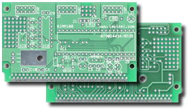
| The picture
above shows 2 Simm100
boards (component and solder side) for the Atmel AVR microcontroller type AT90S8535. |

| The picture above shows the Simm100 board mounted with an AT90S8535, MAX232, MAX701, Reset button and IDC connectors for RS-232, ADC and ISP (In System Programmable). To improve EMI, the board has a ground layer and a separate ground layer for the ADC for a stable Analog Conversion. |
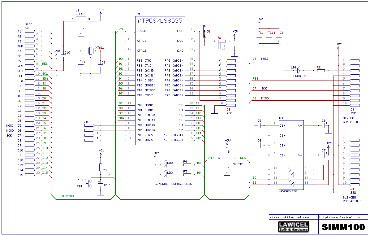
| REV.A Schematics
|
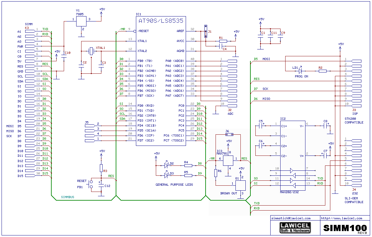
REV.B Schematics
|
Click on the Schematics to enlarge
 |
SIMM100 REV.B
was made in August 2000.
|
| The picture above left shows that it is now possible to add a standard Brown out reset device (similar to those used on e.g. DT103/104/107). Since the normal MAX701 has a separate input pin and an output pin for reset, you need to connect these signals together and that is done with the jumper. |
Assembling Instructions For minimum operation you have to install IC1, XTAL, C1, C2, C3, C11, C12 & R3. The XTAL can be exchanged to a resonator, then C2 and C3 can be omitted. When using the RC Reset (C12 / R3), you also need to install jumper J6 (Rev.B board only) or jumper pin 1 & 6 of IC3 (Rev.A board only) , so the reset signal reaches the microcontroller. You can also add the PB1 pushbutton for a manual RESET if you do not have that on any other place (like e.g. on the DT003/DT006). If you need a bit better RESET (due to that you have other hardware in the system like EEPROM etc. and you want to guarantee that the microcontroller doesn't write to the EEPROM when voltage is too low, then you shall install the Brownout device Q1 and the resistor R6 (Rev.B board only). If you need the best RESET performance with a delayed RESET of 200-300mS, you should not install C12 / R3 or Q1 / R6, instead just install the IC3 (MAX701). Then if you need ISP (In System Programmable) with a Kanda / Atmel STK200 compatible programmer, you need to install J2 and if you like to have indication when programming etc. also R2 and LD1. If you want to use the ADC of the AT90S8535, then install R1 and C4 and optionally the J2 IDC connector. Jumper J1 is by default applying 5VDC to the AREF of the ADC and if you need any other reference voltage, cut that wire open on the board and install J1, so you can select a different reference voltage. pin 9 on the J1 connector could then be used for applying the new voltage reference. There is also a very small Prototype/Experiment area and one of the pads are connected to 0VDC (GND) and the other 5VDC (VCC). To add on board RS-232, you need to install IC2, C5, C6, C7, C8, C9 and the J4 IDC connector. The J4 IDC connector is pin compatible with the SLI-OEM from Wirz (SLI-OEM was removed from Wirz line 2004), so adding a straight ribbon cable between the SIMM100 and the SLI-OEM makes it simple and easy to use a serial LCD. If you do not have access to 5VDC and would like to use e.g. 9-12VDC then install the voltage regulator V1 and capacitor C10. Finally the 2 user definable / general purpose LEDs (LD2 & LD3) plus the resistors for them (R4 & R5) could be mounted and controlled via PC0 & PC1 of the microcontroller, note that they sink current into the microcontroller, so turning them on need a LOW output (0VDC) and turning them off needs a HIGH output (5VDC). J5 is also a small 4 pin connector for the rest of the PD port (PD4-7) that isn't routed out the the SimmStick bus. |
Component Values |
| IC1 | Microcontroller type AVR AT90S8535 or simular |
| IC2 | RS-232 Tranceiver type MAX202/232 |
| IC3 | Reset circuit type MAX701 |
| C1, C4, C9, C10, C11 |
100nF (same as 0.1uF) |
| C2, C3 | 22pF (15-30pF) |
| C5, C6, C7, C8 |
1uF (if MAX232) or 0.1uF (if MAX202) |
| C12 | 4.7uF to 10uF depending on reset delay |
| R1 | 100 ohms |
| R2, R4, R5 | 1k ohms |
| R3 | 10k ohms |
| R6 | 10k ohms (Rev.B only) |
| XTAL1 | What ever frequency you need (Chrystal or Resonator) |
| V1 | 5VDC/1A voltage regulator type TO220 with screw for proper cooling |
| LD1 | LED for indicating ISP programming, normally 3mm RED |
| LD2, LD3 | LEDs for general purpose 3mm, color is up to you |
| J1 | Jumper 3*1 pins |
| J2,J3,J4 | 10pin IDC connector |
| J5 | Connector 4*1 pins |
| J6 | Jumper 2*1 pins (Rev.B only) |
| PB1 | Reset push button |
| Q1 | Brownout (Rev.B only) type Panasonic MN13811-S (O/C) or similar. |
| Demosoftware written in BASCOM-AVR is availible in zip format here (includes Basic source file and hex file). This simple program demonstrates how the on-board LED's can be turned on and off. |
| LAWICEL AB Box 3 SE-282 21 TYRINGE SWEDEN |
Telefon: +46 (0)451-59877 Fax: +46 (0)451-59878 http://www.lawicel.se |
| BACK |
| © Copyright 1997-2007
LAWICEL AB. All rights reserved. Images and text used on this page may not be copied without written approval from LAWICEL AB. Information in this document is subject to change without notice. Other products and companies referred to herein are trademarks or registered trademarks of their respective companies or mark holders. |
Last updated on the 2nd of March 2007